
ZonXin Auto Parts
Shandong ZonXin Auto Parts CO.,LTD
 Mobile|Whatsapp|Wechat:
0086 136 8860 8190
Shandong ZonXin Auto Parts CO.,LTD
Mobile|Whatsapp|Wechat:
0086 136 8860 8190
Technical Field
The present invention relates to the technical field of vehicle suspension systems, in particular to an air suspension lifting structure, and further relates to an assembly method for the air suspension lifting structure.
Background Technology
Existing semi-trailer lifting mechanisms generally adopt air suspension systems, in which an axle is lifted or lowered through a lifting air bag. When the vehicle is traveling without load, one or two axles can be lifted to reduce friction between the tires and the ground, thereby effectively reducing tire wear, extending service life, reducing the turning radius of the vehicle, and lowering fuel consumption. When the vehicle is fully loaded, the lifted axle is automatically lowered to ensure vehicle safety.
During installation of existing lifting air bag brackets, due to the small gap between the upper bracket and lower bracket, or between the upper bracket and fixing frame, washers arranged therebetween are difficult to align and secure during installation and are prone to falling off, thereby causing difficulty in bolt installation. Rotation of the upper bracket easily causes friction damage to the pin shaft. Long-term use reduces the cross-sectional area of the pin shaft, creating a safety hazard of fracture. In addition, existing structural forms are relatively scattered as a whole, nuts are prone to loosening and falling off, and overall safety performance is relatively low.
Summary of the Invention
To solve the above technical problems, the present invention provides an assembly method for an air suspension lifting structure. The technical problems solved include: difficulty in aligning and fixing washers when installing the lifting air bag bracket on the leaf spring, making bolt installation difficult; and friction damage caused by the rotation of the upper bracket against the pin shaft.
To solve the above technical problems, the present invention adopts the following technical solution:
The air suspension lifting structure comprises:
A lower bracket, wherein pin holes A are formed on both sides of the lower bracket;
An upper bracket, wherein the upper bracket is arranged inside the lower bracket, and pin holes B are formed on both sides of the upper bracket. A male-female bushing assembly is sleeved inside the pin holes B. The male-female bushing assembly includes a male bushing and a female bushing fitted together in a sleeved manner. The male bushing includes a first sleeve and a first washer integrally formed with one end face of the first sleeve. The female bushing includes a second sleeve and a second washer integrally formed with one end face of the second sleeve;
A fixing frame, wherein the fixing frame is arranged inside the upper bracket, and pin holes C are formed on the fixing frame;
Bolts, wherein the bolts pass through pin holes A, pin holes C, and the first sleeve.
Further, the male-female bushing assembly is made of wear-resistant polymer material.
Further, the wear-resistant polymer material is one of nylon, high-strength modified epoxy resin, POM polyoxymethylene, PC-ABS composite material, PC polycarbonate, or PEEK polyether ether ketone.
Further, the lower bracket includes two symmetrically arranged transverse plates A, and a connecting plate A arranged between the two transverse plates A, wherein the pin holes A are formed on the transverse plates A.
Further, the upper bracket includes two symmetrically arranged transverse plates B, and a connecting plate B arranged between the two transverse plates B, wherein the pin holes B are formed on the transverse plates B.
Further, one of the first sleeve and second sleeve is provided with an engaging groove, while the other is provided with an engaging protrusion matched with the engaging groove.
Further, the cross-section of the engaging groove is triangular or semicircular.
Further, a locking member for engaging the bolt head is fixedly arranged on the outer side of the lower bracket adjacent to pin holes A.
Further, the bolt head is of a hexagonal structure.
Assembly Method
The present invention further provides an assembly method adopting any of the above-mentioned air suspension lifting structures, comprising the following steps:
Step 1
Sleeve the second sleeve of the female bushing into the pin hole B, such that the second washer is positioned on one side of the upper bracket.
Step 2
Sleeve the first sleeve of the male bushing into the second sleeve, with the engaging protrusion engaged within the engaging groove, such that the first washer is positioned on the opposite side of the upper bracket.
Step 3
Align pin holes A, the first sleeve, and pin holes C concentrically, pass the bolt through pin holes A, the first sleeve, and pin holes C, place the bolt head within the locking member, and secure the bolt using a nut.
Beneficial Effects of the Invention
The present invention has the following beneficial effects:
By arranging the male-female bushing assembly and clamping the upper bracket between the bushings, the problem of difficult washer alignment and fixation is solved, thereby facilitating installation, accelerating assembly speed, and improving work efficiency.
In addition, the problem of friction damage between the upper bracket and the bolt is solved. By arranging sleeves, direct contact between the upper bracket and the bolt is prevented, thereby avoiding rigid damage that could cause bolt fracture and improving structural safety performance.
Furthermore, anti-loosening engaging protrusions and engaging grooves are arranged between the male and female bushings.
By arranging the locking member, the bolt is fixed in position to prevent rotation that could otherwise loosen and detach the nut, thereby improving overall structural integrity and further enhancing safety.
Description of the Drawings
Figure 1 is an exploded structural schematic diagram of the present invention;
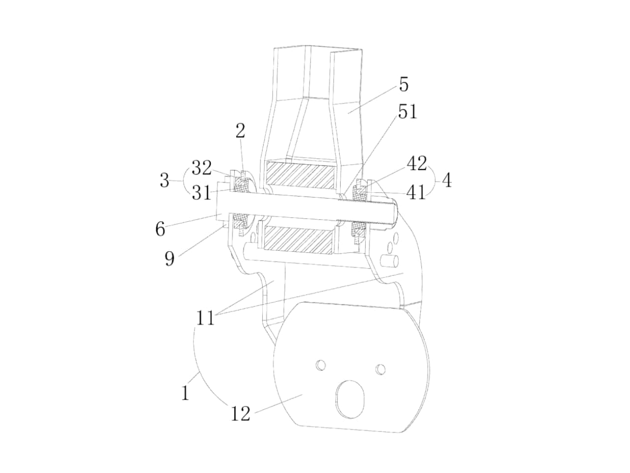
Figure 2 is a sectional structural schematic diagram after assembly of the present invention;
Figure 3 is an exploded sectional structural schematic diagram of the male-female bushing assembly and pin holes A.
Reference numerals in the drawings:
Lower bracket
Transverse plate A
Connecting plate A
Pin hole A
Upper bracket
Transverse plate B
Connecting plate B
Pin hole B
Male bushing
First sleeve
First washer
Female bushing
Second sleeve
Second washer
Fixing frame
Pin hole C
Bolt
Engaging groove
Engaging protrusion
Locking member
Detailed Description
To make the objectives, technical solutions, and advantages of the present invention clearer, the present invention is further described in detail below with reference to the accompanying drawings and embodiments, so that the public can better understand the implementation method of the invention.
The air suspension lifting structure comprises a lower bracket 1, wherein pin holes A13 are formed on both sides of the lower bracket 1.
An upper bracket 2 is arranged inside the lower bracket 1. Pin holes B23 are formed on both sides of the upper bracket 2. A male-female bushing assembly is sleeved inside the pin holes B23. The male-female bushing assembly includes a male bushing 3 and a female bushing 4 fitted together in a sleeved manner.
The male bushing 3 includes a first sleeve 31 and a first washer 32 integrally formed with one end face of the first sleeve 31.
The female bushing 4 includes a second sleeve 41 and a second washer 42 integrally formed with one end face of the second sleeve 41.
By arranging the male-female bushing assembly within the pin holes B23, the assembly is securely clamped onto the upper bracket 2, preventing it from easily falling off during installation, thereby improving installation efficiency and saving time.
The fixing frame 5 is arranged inside the upper bracket 2, and pin holes C51 are formed on the fixing frame 5.
Bolts 6 pass through pin holes A13, pin holes C51, and the first sleeve 31, thereby integrating the entire structure into one assembly.
The male-female bushing assembly is made of wear-resistant polymer material. In this embodiment, the material is nylon. In other embodiments, high-strength modified epoxy resin, POM polyoxymethylene, PC-ABS composite material, PC polycarbonate, or PEEK polyether ether ketone may also be used.
The material properties themselves alleviate rigid contact between the upper bracket 2 and the bolts 6, between the upper bracket 2 and the lower bracket 1, and between the upper bracket 2 and the fixing frame 5, thereby providing a lubricating effect.
The lower bracket 1 includes two symmetrically arranged transverse plates A11 and a connecting plate A12 arranged therebetween, wherein pin holes A13 are formed on the transverse plates A11.
The upper bracket 2 includes two symmetrically arranged transverse plates B21 and a connecting plate B22 arranged therebetween, wherein pin holes B23 are formed on the transverse plates B21.
This structural design reduces weight while ensuring the hinged relationship among the upper bracket 2, lower bracket 1, and fixing frame 5.
In this embodiment, an engaging groove 7 is formed on the outer circumferential wall of the first sleeve 31, while an engaging protrusion 8 matched with the engaging groove 7 is formed on the inner circumferential wall of the second sleeve 41.
In other embodiments, the positions of the engaging groove 7 and engaging protrusion 8 may be exchanged.
Through cooperation between the engaging groove 7 and engaging protrusion 8, the male bushing 3 and female bushing 4 are combined into an integral structure and clamped onto the transverse plate B21.
The cross-section of the engaging groove 7 is triangular or semicircular to facilitate insertion of the engaging protrusion 8 into the engaging groove 7.
A locking member 9 for engaging the head of the bolt 6 is fixedly arranged on the outer side of the lower bracket 1 adjacent to pin holes A13.
The bolt head of the bolt 6 has a hexagonal structure. By arranging the locking member 9, the bolt 6 is fixed to prevent rotation that could otherwise loosen and detach the nut, thereby improving overall integrity.
Assembly Method of the Air Suspension Lifting Structure
The assembly method of the air suspension lifting structure adopts the structure described in the above embodiments and comprises the following steps:
Step 1
Sleeve the second sleeve 41 of the female bushing 4 into the pin holes B23, engage the engaging protrusion 8 within the engaging groove 7, and position the second washer 42 on one side of the upper bracket 2.
Step 2
Sleeve the first sleeve 31 of the male bushing 3 into the second sleeve 41, engage the engaging protrusion 8 within the engaging groove 7, and position the first washer 32 on the opposite side of the upper bracket 2.
Step 3
Align pin holes A13, the first sleeve 31, and pin holes C51 concentrically, pass the bolt through pin holes A13, the first sleeve 31, and pin holes C51, place the head of the bolt 6 within the locking member 9, and secure the bolt using a nut.
In the description of the present invention, directional terms such as “center,” “upper,” “lower,” “left,” “right,” “front,” “rear,” “outer,” “clockwise,” and “counterclockwise” are based on the orientations shown in the accompanying drawings and are merely for convenience of description and simplification. They do not indicate or imply that the referenced device or element must have a specific orientation or must be constructed and operated in a specific orientation, and therefore should not be construed as limiting the scope of protection of the present invention.
In addition, terms such as “first,” “second,” and “third” are used only for descriptive purposes and should not be interpreted as indicating or implying relative importance.
Although the present invention has been described based on a limited number of embodiments, those skilled in the art can conceive of other embodiments within the scope of the present invention based on the above description.
Liaison:Eva
Mobile:0086 136 8860 8190
Phone:0086 0537 7338178
Email:[email protected]
Address:Liangshan County,Shandong Province,China
