
ZonXin Auto Parts
Shandong ZonXin Auto Parts CO.,LTD
 Mobile|Whatsapp|Wechat:
0086 136 8860 8190
Shandong ZonXin Auto Parts CO.,LTD
Mobile|Whatsapp|Wechat:
0086 136 8860 8190
Technical Field
The utility model relates to the technical field of pneumatic steering axles, and particularly relates to a pneumatic steering axle suitable for low-bed trailers.
Background Technology
Low-bed trailers are mainly used for transporting certain non-detachable objects, such as excavators, loaders, harvesters, and similar equipment. Low-bed trailers have advantages such as simple structure, convenient use, easy maintenance, and large load-bearing capacity.
The length of a flatbed trailer is generally between 4 and 13 meters, and transportation is usually carried out by one or more flatbed trailers combined with a tractor vehicle for cargo transportation or large equipment handling.
A steering axle is an indispensable device for steering various vehicles. When a low-bed trailer turns during driving and the centrifugal force exceeds a certain value, the pneumatic unit of the axle controls the axle to start steering, while the axle automatically returns to its original position during straight-line driving.
Compared with centrifugal self-steering axles, pneumatic steering axles have a more reliable steering mechanism. However, because the deck height of low-bed trailers is relatively low, traditional pneumatic steering axles face the problem that there is insufficient space for arranging the lifting device. Redesigning the trailer deck height would result in excessive costs, and increasing the deck height may also cause transportation instability.
Summary of the Utility Model
In view of the above problems, the utility model proposes a pneumatic steering axle suitable for low-bed trailers. By improving the traditional pneumatic steering axle, it can better adapt to low-bed trailers.
To achieve the above purpose, the utility model provides the following technical solution.
A pneumatic steering axle suitable for low-bed trailers comprises:
A pneumatic steering axle;
Lifting beams;
Lifting air bags.
Wherein:
A steering air bag horizontally protruding outward is fixed on the cross beam of the pneumatic steering axle.
There are two lifting beams, both horizontally fixed on the cross beam and positioned on the same side of the pneumatic steering axle as the steering air bag. The two lifting beams are respectively distributed above both sides of the steering air bag, and the protruding length of the lifting beams does not exceed the steering air bag.
The lifting air bags are arranged in two groups and are respectively fixed at the ends of the two lifting beams, with the lifting air bags facing upward.
Further, the lifting beams are rectangular metal tubes, which not only provide excellent bending resistance but also help reduce weight.
Further, the lifting air bags are short-stroke bellows-type air bags, which are beneficial for increasing the lifting stroke of the axle while occupying less space.
Further, the rear ends of the lifting beams are fixed on the upper surface of the cross beam, while the lifting air bags are fixed at the front ends of the lifting beams.
Further, the lower surfaces of the rear ends of the lifting beams are provided with arc-shaped grooves. The arc-shaped grooves closely fit the outer wall of the cross beam and are fixedly connected thereto.
Beneficial Effects
Compared with the prior art, the utility model has the following beneficial effects:
The pneumatic steering axle suitable for low-bed trailers provided by the utility model arranges the lifting beams and lifting air bags on both sides of the original steering air bag of the steering axle, thereby fully utilizing the available space and reducing additional space occupation.
In addition, by adopting short-stroke bellows-type air bags as the lifting air bags, the lifting and lowering functions of the pneumatic steering axle can be achieved while overcoming the problem that traditional pneumatic steering axles lack sufficient installation space for lifting devices.
Furthermore, arranging the lifting beams above both sides of the steering air bag avoids interference with the steering air bag during operation and non-operation states, thereby preventing the steering air bag from being affected by the lifting beams.
Description of the Drawings
The accompanying drawings, which form part of this specification, are used to further explain the utility model. The exemplary embodiments and descriptions are intended to explain the utility model and do not constitute improper limitations on the utility model.
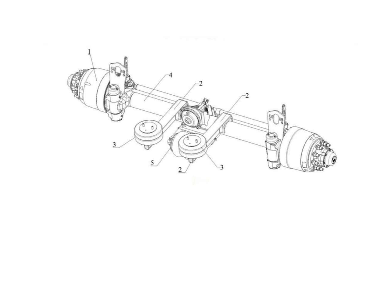
Figure 1 is a structural schematic diagram of the pneumatic steering axle suitable for low-bed trailers according to the embodiments below.
Reference numerals in the figure represent:
Pneumatic steering axle
Lifting beam
Lifting air bag
Cross beam
Steering air bag
Detailed Description
For convenience of description, directional terms such as “upper,” “lower,” “left,” and “right” used in the utility model only correspond to the directions shown in the drawings. They are merely used for convenient description and simplification, and do not indicate or imply that the referenced devices or elements must possess specific orientations or be constructed and operated in specific orientations. Therefore, these terms should not be interpreted as limitations on the utility model.
The technical solution of the utility model is further described below with reference to the accompanying drawings and specific embodiments.
Referring to Figure 1, an example of a pneumatic steering axle suitable for low-bed trailers includes a pneumatic steering axle 1, lifting beams 2, and lifting air bags 3.
A steering air bag 5 protruding horizontally outward is fixed at the middle position of the cross beam 4 of the pneumatic steering axle 1.
There are two lifting beams 2. The rear ends of the lifting beams 2 are fixed on the upper surface of the cross beam 4. Both lifting beams 2 are horizontally fixed on the cross beam 4 and positioned on the same side of the pneumatic steering axle 1 as the steering air bag 5.
The two lifting beams 2 are respectively arranged above both sides of the steering air bag 5, and the protruding length of the lifting beams 2 does not exceed the steering air bag 5.
The lifting air bags 3 are arranged in two groups and respectively fixed at the front ends of the lifting beams 2, with the lifting air bags 3 facing upward.
In a more preferred embodiment, the lifting air bags 3 are short-stroke bellows-type air bags, which are beneficial not only for increasing the lifting stroke of the axle but also for occupying less space.
The pneumatic steering axle suitable for low-bed trailers in this embodiment arranges the lifting beams 2 and lifting air bags 3 on both sides of the original steering air bag 5 of the steering axle, thereby fully utilizing the available space and reducing excessive additional space occupation.
In addition, by using short-stroke bellows-type air bags as the lifting air bags 3, the lifting and lowering functions of the pneumatic steering axle are achieved while overcoming the problem that traditional pneumatic steering axles lack sufficient installation space for lifting devices.
Furthermore, arranging the lifting beams 2 above both sides of the steering air bag 5 avoids interference with the steering air bag 5 during operation and non-operation states, thereby preventing the steering air bag 5 from being affected by the lifting beams 2.
Continuing to refer to Figure 1, in another embodiment, the lifting beams 2 are rectangular steel tubes measuring 50 mm × 100 mm (width × length), which provide good bending resistance while helping reduce weight.
Continuing to refer to Figure 1, in another embodiment, the lower surfaces of the rear ends of the lifting beams 2 are provided with arc-shaped grooves. The arc-shaped grooves closely fit the outer wall of the cross beam 4 and are fixedly connected thereto.
Finally, it should be noted that any modifications, equivalent substitutions, improvements, and the like made within the spirit and principles of the utility model shall fall within the protection scope of the utility model.
Although the specific embodiments of the utility model have been described with reference to the accompanying drawings, they do not limit the protection scope of the utility model. Those skilled in the art should understand that various modifications or variations can still be made based on the technical solution of the utility model without creative effort, and these modifications or variations shall still fall within the protection scope of the utility model.
Liaison:Eva
Mobile:0086 136 8860 8190
Phone:0086 0537 7338178
Email:[email protected]
Address:Liangshan County,Shandong Province,China
