
ZonXin Auto Parts
Shandong ZonXin Auto Parts CO.,LTD
 Mobile|Whatsapp|Wechat:
0086 136 8860 8190
Shandong ZonXin Auto Parts CO.,LTD
Mobile|Whatsapp|Wechat:
0086 136 8860 8190
Technical Field
This utility model belongs to the field of automotive air suspension systems, and particularly relates to a front axle lift air suspension system.
Background Technology
Both domestic and international road traffic regulations impose limits on the axle load of each individual axle of heavy-duty vehicles. As the development trend of heavy-duty trucks moves toward higher payload capacity, it becomes necessary to increase the number of axles to ensure that axle loads do not exceed regulatory limits when the vehicle is fully loaded.
However, when the vehicle operates under no-load or light-load conditions, an increased number of axles leads to several disadvantages, such as higher fuel consumption, increased tire wear, reduced vehicle speed, and a larger minimum turning radius.
Summary of the Invention
The purpose of this utility model is to address the shortcomings of the existing technology by providing a front axle lift air suspension system capable of lifting the axle with flexible and stable operation.
To achieve this objective, the technical solution adopted is as follows:
The front axle lift air suspension system comprises a vehicle frame, a lifting bracket mounted at the lower end of the frame, load-bearing air springs, and a bent guide arm.
The load-bearing air springs include a left air spring and a right air spring. The lower horizontal section of the guide arm is connected to the lower end of the right air spring, and the upper end of the right air spring is fixedly connected to the vehicle frame. The upper horizontal section of the guide arm is fixedly connected to the axle.
The left end of the guide arm is hinged to a bracket pin shaft at the lower part of the lifting bracket. The upper part of the lifting bracket is connected to a shock absorber via a spherical joint, and the other end of the shock absorber is connected to the axle.
A left air spring is arranged on the left side of the lifting bracket and connected to the vehicle frame. The lower end of the left air spring is connected to a lifting arm, and the other end of the lifting arm is fixedly connected to the lower end of the axle.
Beneficial Effects
The arrangement of the left air spring reduces the load borne by the right air spring, preventing lateral deformation of the right air spring and avoiding lateral swinging of the guide arm.
The coordinated operation of the left and right air springs enables flexible lifting and lowering of the axle with strong stability, thereby improving vehicle safety and reducing overall operating and maintenance costs.
After the axle is lifted, tire wear is reduced, fuel consumption is lowered, and vehicle maneuverability—especially during turning—is improved.
Description of Drawings
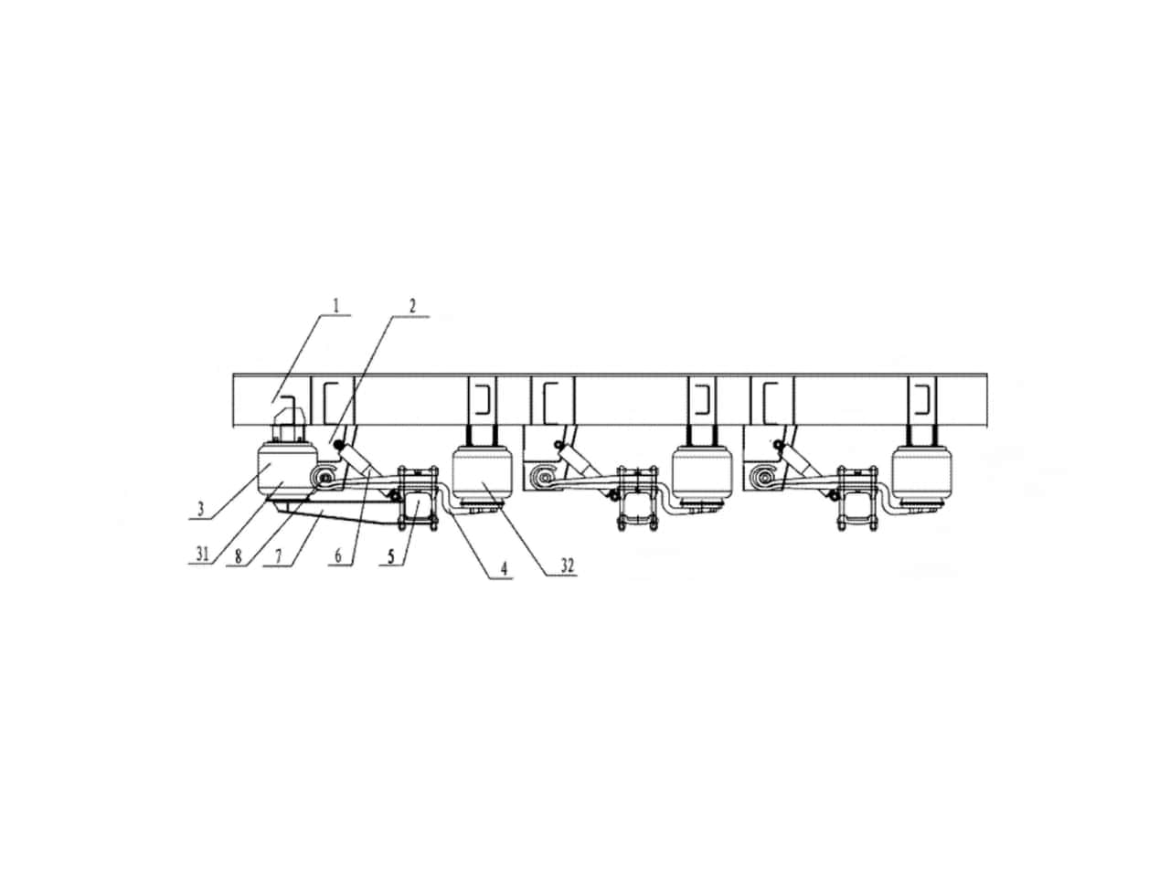
Figure 1 is a schematic structural diagram of the utility model. In the figure:
Vehicle frame
Lifting bracket
Load-bearing air spring
31. Left air spring
32. Right air spring
Guide arm
Axle
Shock absorber
Lifting arm
Bracket pin shaft
Detailed Description
As shown in Figure 1, the front axle lift air suspension system includes a vehicle frame (1), a lifting bracket (2) mounted at the lower end of the frame (1), load-bearing air springs (3), and a bent guide arm (4).
The load-bearing air springs (3) include a left air spring (31) and a right air spring (32). The lower horizontal section of the guide arm (4) is connected to the lower end of the right air spring (32), while the upper end of the right air spring (32) is fixedly connected to the vehicle frame (1). The upper horizontal section of the guide arm (4) is fixedly connected to the axle (5).
The left end of the guide arm (4) is hinged to the bracket pin shaft (8) at the lower part of the lifting bracket (2). The upper part of the lifting bracket (2) is connected to a shock absorber (6) via a spherical joint, and the other end of the shock absorber (6) is connected to the axle (5).
A left air spring (31) is arranged on the left side of the lifting bracket (2) and connected to the vehicle frame (1). The lower end of the left air spring (31) is connected to a lifting arm (7), and the other end of the lifting arm (7) is fixedly connected to the lower end of the axle (5).
When the vehicle is unloaded or lightly loaded, the driver presses the front axle lift switch in the cab. The left air spring (31) is inflated, pushing one end of the lifting arm (7) downward, while the other end of the lifting arm (7) drives the axle (5) to rotate upward around the bracket pin shaft (8). At the same time, the right air spring (32) is deflated, causing the guide arm (4), connected to the lower end of the right air spring (32), to rotate upward around the bracket pin shaft (8), thereby quickly lifting the axle (5) and wheels.
When the driver presses the axle lowering button, the left air spring (31) is deflated while the right air spring (32) is inflated, causing the guide arm (4) and wheels to be quickly lowered.
Except for the technical features described above, all other features belong to the prior art known to those skilled in the field.
Liaison:Eva
Mobile:0086 136 8860 8190
Phone:0086 0537 7338178
Email:[email protected]
Address:Liangshan County,Shandong Province,China
