
ZonXin Auto Parts
Shandong ZonXin Auto Parts CO.,LTD
 Mobile|Whatsapp|Wechat:
0086 136 8860 8190
Shandong ZonXin Auto Parts CO.,LTD
Mobile|Whatsapp|Wechat:
0086 136 8860 8190
Technical Field
The utility model relates to the technical field of air suspensions, and particularly relates to an air suspension bracket assembly.
Background Technology
Air suspension is a suspension system that uses air springs instead of traditional leaf springs. Due to its advantages such as light weight, good ride comfort, and high stability, it is widely used in buses and trucks. At present, it is also increasingly applied to trailers, especially tank trailers used for transporting hazardous materials, where the suspension is connected to the vehicle body through a bracket assembly.
However, during the use of existing air suspension bracket assemblies, the bracket is subjected to external compression forces and frequent lifting movements, causing the air suspension to operate repeatedly. This shortens the service life of the air suspension. In addition, long-term use leads to severe wear of the springs and telescopic rods inside the suspension.
Therefore, it is necessary to provide an air suspension bracket assembly to solve the above technical problems.
Summary of the Utility Model
The utility model provides an air suspension bracket assembly, which solves the problems that frequent operation of the air suspension shortens its service life and causes serious wear of the internal springs and telescopic rods in existing air suspension bracket assemblies.
To achieve the above objective, the utility model provides an air suspension bracket assembly comprising:
a bracket body,
a wheel hub fixedly connected to one side of the bracket body,
a C-shaped seat plate connected to the top of the bracket body,
suspension bodies connected respectively to both sides of the C-shaped seat plate.
A vibration damping mechanism is installed between the bracket body and the C-shaped seat plate. The vibration damping mechanism includes:
two sliding grooves,
sliding blocks inserted within the sliding grooves,
arc-shaped support plates fixedly connected to the sliding blocks.
The inner top end of the C-shaped seat plate is fixedly connected with two telescopic outer rods, inside which damping springs are fixedly connected. The bottom ends of the damping springs are fixedly connected with T-shaped support rods, and the T-shaped support rods are fixedly connected with the top ends of the arc-shaped support plates.
The T-shaped support rods are symmetrically arranged about the central axis of the arc-shaped support plates. The T-shaped support rods, damping springs, and telescopic outer rods together form an elastic telescopic structure.
A lubrication mechanism is installed at the top of the C-shaped seat plate, and fixing mechanisms are installed on both sides of the C-shaped seat plate.
Preferred Embodiments
1. Structural Symmetry
The telescopic outer rods are symmetrically arranged about the central axis of the C-shaped seat plate. The arc-shaped support plates are engaged with the top end of the bracket body.
2. Lubrication Mechanism
The lubrication mechanism includes:
an oil storage tank connected to the top of the C-shaped seat plate,
a filling port formed at the top of the oil storage tank,
a rubber plug fitted inside the filling port,
a sealing plate fixedly connected to the top of the rubber plug,
oil delivery pipes embedded on both sides of the oil storage tank.
The oil delivery pipes are embedded and connected with the interiors of the suspension bodies.
3. Sealing Structure
The sealing plate and the filling port form a detachable structure through the rubber plug. The oil storage tank is fixedly connected with the C-shaped seat plate.
4. Fixing Mechanism
The fixing mechanism includes:
two connecting pipes welded to both sides of the C-shaped seat plate,
sleeves sleeved on the surfaces of the connecting pipes,
threaded rods threaded inside the connecting pipes,
baffle plates fixedly connected to one ends of the threaded rods.
The sleeves are welded to the bottom ends of the suspension bodies.
5. Detachable Structure
The baffle plates form detachable structures with the connecting pipes through the threaded rods. The connecting pipes are symmetrically arranged about the central axis of the C-shaped seat plate.
Beneficial Effects
Compared with the prior art, the utility model has the following beneficial effects:
1. Improved Vibration Damping Performance
Under the action of the vibration damping mechanism, when the bracket body is compressed by external force, the bracket body pushes the arc-shaped support plate upward. The sliding block moves upward inside the sliding groove and compresses the damping spring.
Through the elastic characteristics of the damping spring:
vibration of the bracket body can be effectively reduced,
the assembly gains better shock absorption performance,
frequent movement of the C-shaped seat plate is prevented,
repeated telescopic operation of the suspension bodies is reduced,
operating frequency of the suspension bodies is lowered,
service life of the suspension bodies is extended.
2. Lubrication and Anti-Rust Function
Through the lubrication mechanism:
lubricating oil can be added into the oil storage tank through the filling port,
the lubricating oil is stored inside the oil storage tank,
the oil is delivered into the suspension bodies through the oil delivery pipes.
This allows:
smoother telescopic movement of the suspension bodies,
prevention of rusting of internal springs during long-term use,
improved service life of the suspension bodies.
3. Convenient Installation and Maintenance
Through the fixing mechanism:
rotating the baffle plate drives the threaded rod to rotate and move inside the connecting pipe,
the sleeve on the surface of the connecting pipe is thereby fixed,
the suspension body can be quickly connected to the C-shaped seat plate,
disassembly of the suspension body becomes more convenient,
maintenance efficiency is improved.
Description of Drawings
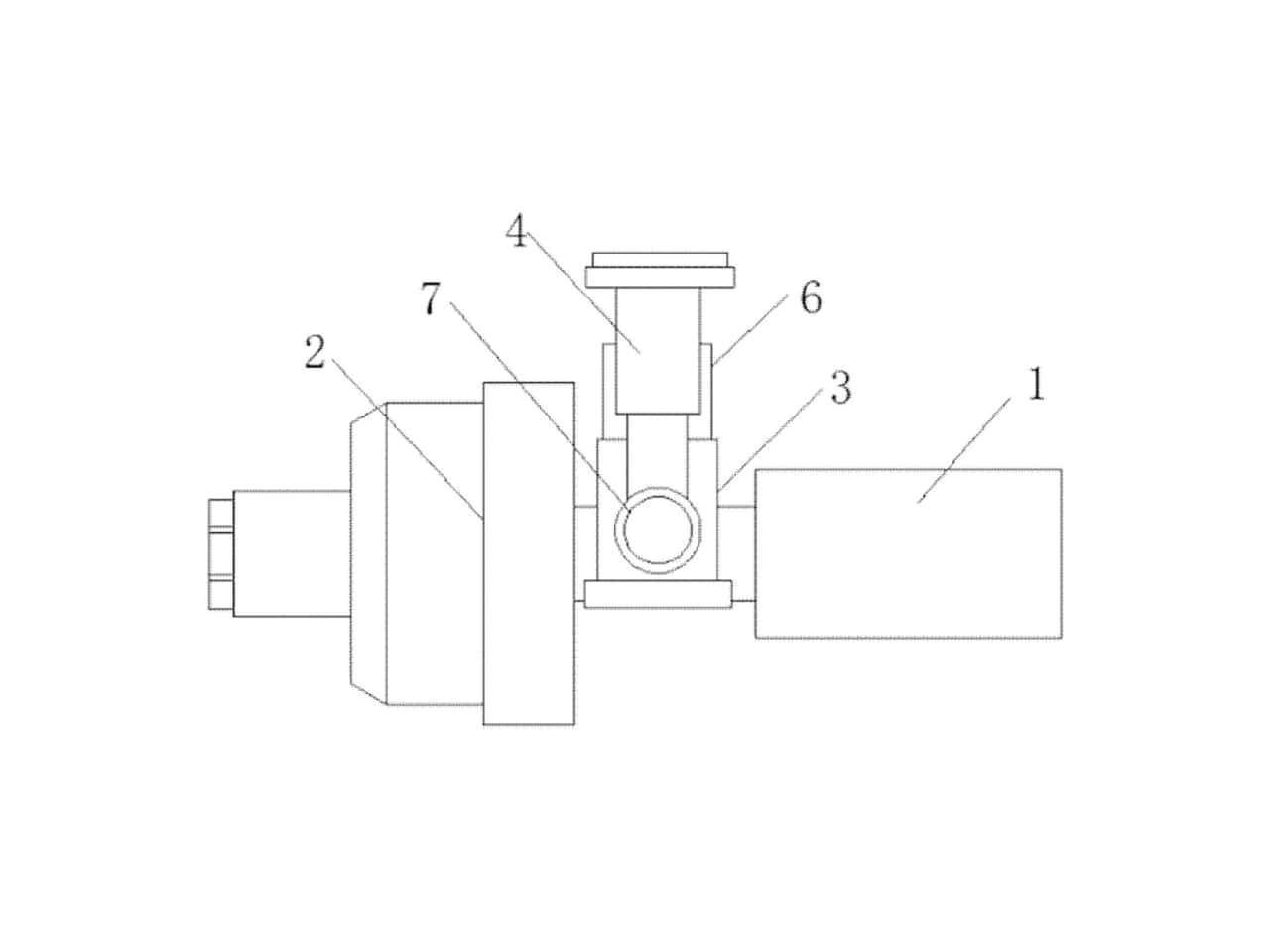
Figure 1: Structural schematic diagram of a preferred embodiment of the air suspension bracket assembly.
Figure 2: Side structural schematic diagram of Figure 1.
Figure 3: Structural schematic diagram of the vibration damping mechanism shown in Figure 1.
Reference Numerals
No.
Component
1 Bracket body
2 Wheel hub
3 C-shaped seat plate
4 Suspension body
5 Vibration damping mechanism
501 Sliding groove
502 Sliding block
503 Arc-shaped support plate
504 Telescopic outer rod
505 Damping spring
506 T-shaped support rod
6 Lubrication mechanism
601 Oil storage tank
602 Filling port
603 Rubber plug
604 Sealing plate
605 Oil delivery pipe
7 Fixing mechanism
701 Connecting pipe
702 Sleeve
703 Threaded rod
704 Baffle plate
Working Principle
First, lubricating oil is added into the oil storage tank through the filling port. The rubber plug at the bottom of the sealing plate is inserted into the filling port for sealing.
The sleeve welded to the bottom end of the suspension body is sleeved onto the connecting pipe on both sides of the C-shaped seat plate. By manually rotating the baffle plate, the threaded rod moves rotationally inside the connecting pipe, thereby fixing the sleeve onto the connecting pipe.
During operation:
lubricating oil inside the oil storage tank flows into the suspension body through the oil delivery pipes,
lubrication ensures smoother telescopic movement and prevents internal spring rusting.
When the bracket body is compressed by external force:
the bracket body pushes the arc-shaped support plate upward,
the sliding block moves upward in the sliding groove,
the damping spring is compressed.
After the external force disappears:
the damping spring pushes the arc-shaped support plate downward,
the arc-shaped support plate presses the bracket body downward,
the structure returns to its original position.
Thus, the working process of the utility model is completed.
The above descriptions are only preferred embodiments of the utility model and do not limit the patent scope of the utility model. Any equivalent structural transformations or equivalent process transformations made according to the specification and drawings of the utility model, or direct or indirect applications in other related technical fields, shall also fall within the protection scope of the utility model patent.
Liaison:Eva
Mobile:0086 136 8860 8190
Phone:0086 0537 7338178
Email:[email protected]
Address:Liangshan County,Shandong Province,China
